ESUS CubeSat — Mechanical Design, Integration, and Qualification Testing
Program: ESUS — CentraleSupelec Space Center for CubeSats
Sponsors: French Space Agency (CNES), Thales Alenia Space
Role: Structural and Thermal Engineer
Project Overview
ESUS is a CentraleSupelec 3U CubeSat scheduled for launch in 2027, developed end-to-end by a team of ~30 engineering students and 5 faculty advisors, with sponsorship and technical support from the French Space Agency and Thales Alenia Space. The mission carries two payloads:
- an interferometer to measure the Sun’s diameter,
- an AI camera that analyzes images onboard and discards frames with excessive cloud cover to reduce memory and power usage.
Along with one other student, we formed the Structure & Thermal team. I was primarily responsible for the structural work, while my teammate focused on thermal aspects; however, the two domains were tightly coupled and required coordination. I built the flight-representative mechanical CAD of ESUS and derived from it the first Structural Model (STM) to validate Phase B (Preliminary Design & Technology Completion) through mechanical qualification activities.
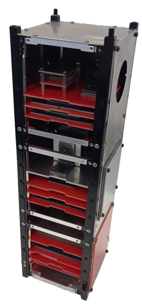
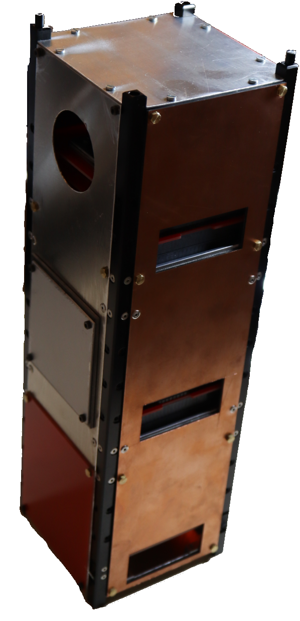
▸ Part 1 - Mechanical Design and Build Read more
Technical contribution
Flight CAD architecture
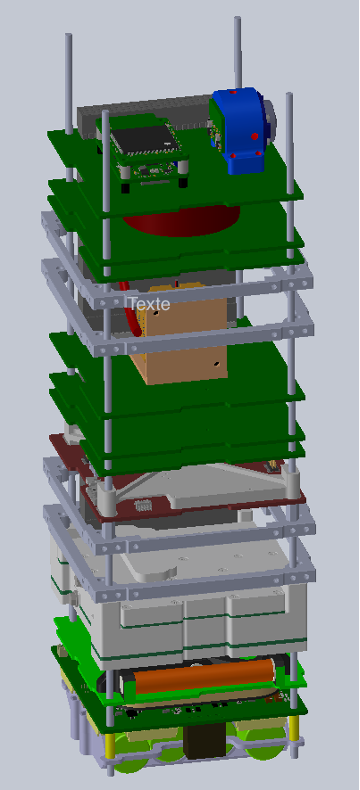
I owned the flight-representative ESUS CAD model, built from real subsystem geometries and internal payload models. This CAD was used to:
- lock deployer interfaces and critical tolerance stack-ups (rails/panels/fasteners) to guarantee clearance and reliable ejection,
- converge subsystem packaging and stack-up to meet mass distribution constraints, ensure connectivity between components, and account for thermal transfer considerations,
- establish the mass-property targets that the STM would need to reproduce,
- prepare the build of the flight model.
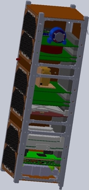
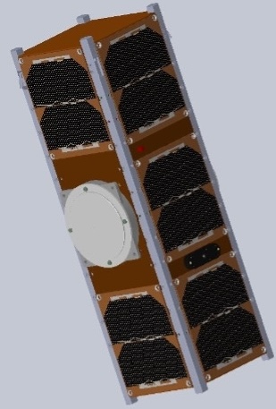
From CAD to STM
STM requirements were to remain compliant with the 3U envelope (340.5 × 100 × 100 mm) and compatible with P-POD-class interfaces via the ISIS iSiPod deployer, while replicating the flight mass distribution and equivalent inertia. Success was defined by matching the external geometry and interface features of the flight configuration, and by achieving system-level mass and inertia behavior with subsystem placement consistent enough to reproduce launch and on-orbit mechanical loads.
During Phase B, several flight components were not yet physically available—especially items provided by CNES and parts of the payload—although we did have the mechanical information needed to model them. Waiting for all flight hardware would have delayed system-level verification by months to years, preventing timely Phase B validation with sponsors.
The solution was to use mass dummies. Even without final hardware, this approach allowed us to validate the mechanical aspects for Phase B:
- deployer interface compatibility and ejection behavior,
- vibration survivability and structural integrity trends (launcher-driven requirements),
- global mass properties (total mass, center of gravity, and inertia behavior).
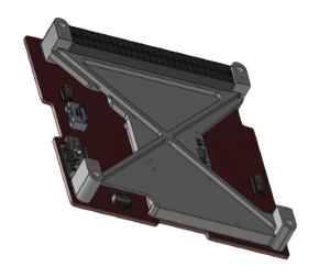
To make the STM representative, dummy masses were sized using datasheet component masses. Their placement followed the real component layout on PCBs, and shapes were sometimes tuned (plates, blocks, butterfly geometries) to better reproduce inertia behavior rather than only matching total mass. This required that I manufactured aluminum or steel parts depending on the required density, using CentraleSupelec’s fabrication laboratory.
STM definition, build, and integration
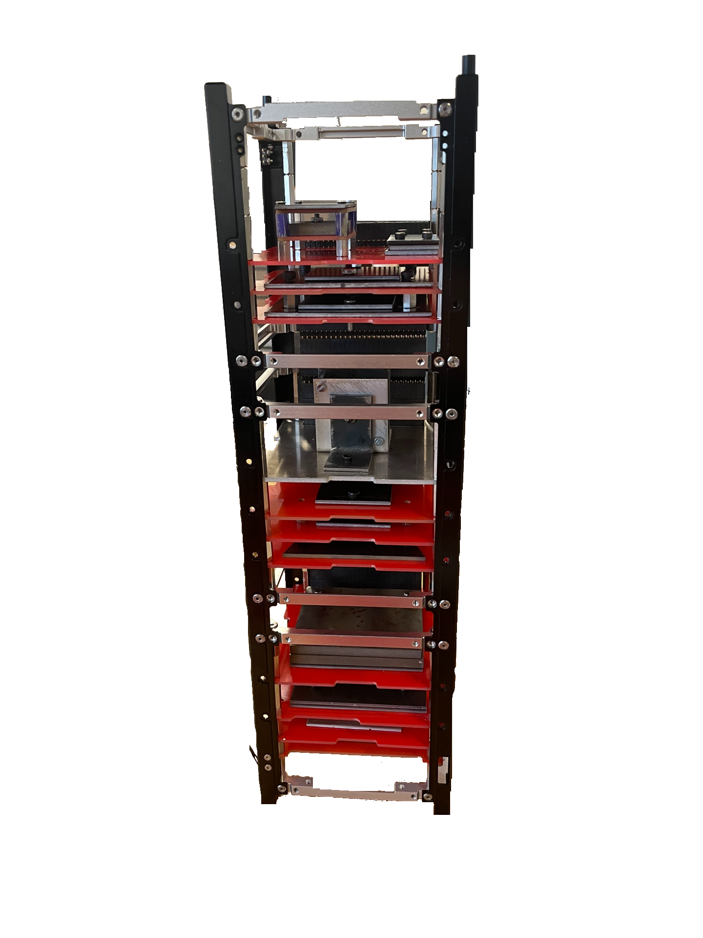
The STM reproduces the CubeSat partitioning of the flight design:
- a primary structure (4 aluminum rails and 4 aluminum frames),
- a card rack represented by steel/aluminum mass dummies mounted on PCB cards (stacked using M3 threaded rods with PC104 spacing logic),
- payload representation using aluminum/steel masses,
- PCB solar panels mounted on the lateral faces,
- S-band antennas represented by steel masses mounted on external aluminum panels.
My results
Thanks to the STM, we obtained experimental measurements of the system mass and center of gravity location. Using the assembled STM, we measured:
- Total mass: 4098 g (target was 4 kg)
- Center of gravity offset relative to the structural geometric center: x = 0 mm, y = 2 mm, z = 7 mm
Conclusion
With this STM now representative of the flight configuration, we can proceed with mechanical testing and use the results to support Phase B validation, provided test outcomes meet expectations.
▸ Part 2 - Mechanical Qualification Testing Read more
Technical contribution
Led the STM mechanical qualification campaign focused on deployer constraints and launcher vibration environments.
I owned the end-to-end engineering work for the STM vibration qualification activity:
- Defined the test approach and acceptance criteria, and ensured compliance with requirements.
- Built the test configuration and instrumentation plan to measure internal structural response.
- Performed integrity assessment using pre-/post-resonance surveys and response analysis to identify any mechanical change.
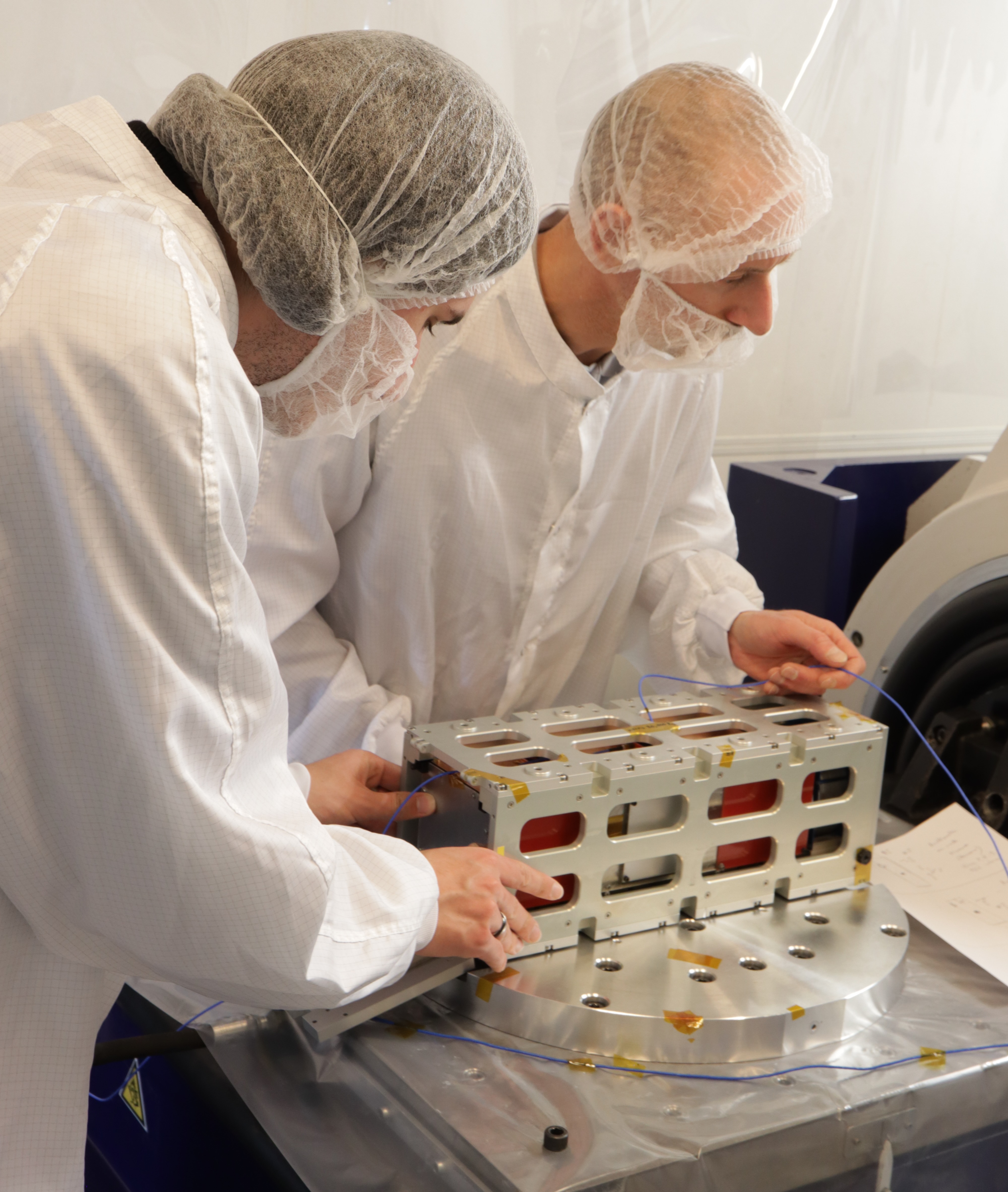
Test setup and instrumentation
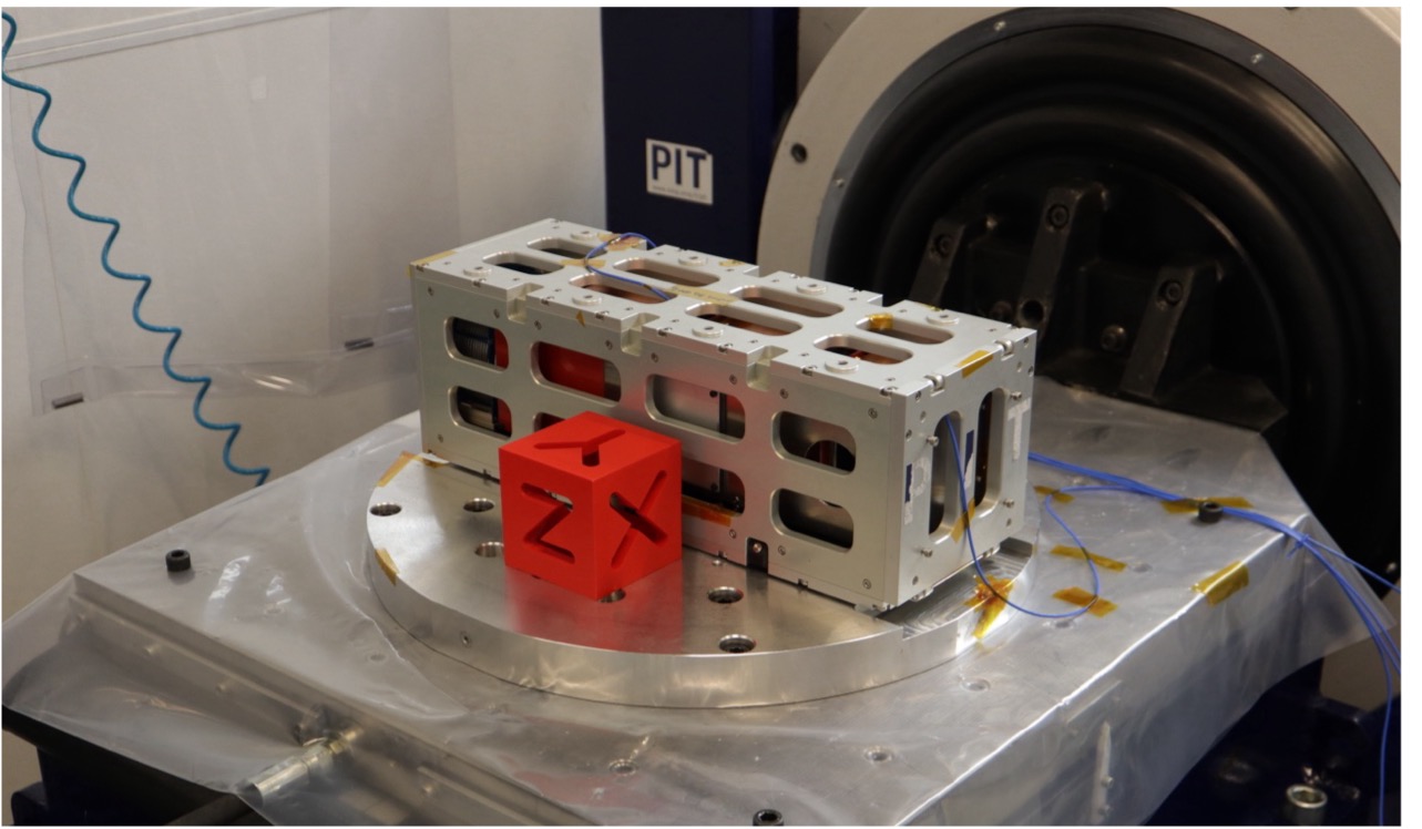
- Reference frame and axes: testing was performed along the CubeSat axes X, Y, Z.
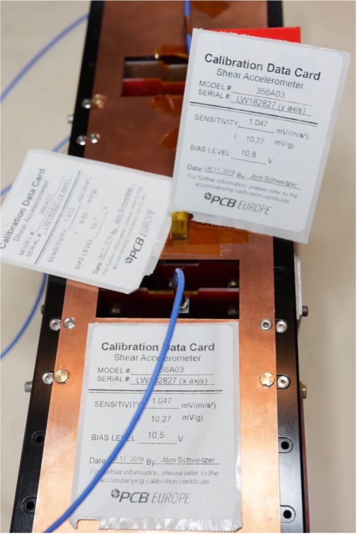
- Instrumentation strategy: I instrumented the STM with tri-axial accelerometers to capture both input control levels and the structural response. The core configuration used four 3-axis accelerometers, including one mounted at the card-rack center.
Test plan and acceptance criteria
I used a structured integrity-check process: run a resonance survey before and after each environment to detect any mechanical change. Because the launcher had not been selected yet, I used the Arianespace VEGA vibration requirements as the reference case (most restrictive at the time).
The resonance survey excites the CubeSat across a wide band to reveal its modes. I performed it before testing and after each test, enabling direct comparison of resonance frequencies and amplitudes. A significant change indicates internal failure or a mechanical-property change (loosening, damage, interface shift).
Resonance survey:
- Input: 0.5 g, 5–2000 Hz, sweep rate 2 oct/min
- Success criterion: frequency shift < 5% relative to the reference spectrum.
Vibration environments:
- Quasi-static load: 13 g per axis at 35 Hz (represents launch accelerations)
- Sinusoidal vibration: 5–125 Hz with amplitude schedule, 2 oct/min (represents launcher oscillations)
- Random vibration: 20–2000 Hz PSD profile, 7.65 gRMS target, 120 s duration (stresses components and validates assembly)
My results
Resonance survey and structural integrity
The first natural frequencies measured on the STM were:
- X axis: 385 Hz
- Y axis: 230 Hz
- Z axis: 290 Hz
This meets the requirement of a first mode > 100 Hz with a safety factor of 2.3.
Quasi-static load performance
From the quasi-static load test, the measured response at the STM accelerometers remained close to the commanded lateral acceleration, indicating an almost unit transfer function between the shaker input and the STM response.
Sinusoidal vibration response
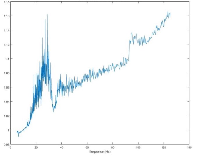
The structure response showed very limited amplification in the 5–120 Hz band:
- Max amplification ~16% (X)
- Max amplification ~18% (Y)
- Max amplification ~15% (Z)
This is consistent with the STM having no structural natural frequency within 5–120 Hz, which is exactly what we want for launcher-driven sinusoidal environments.
Random vibration performance
The achieved control levels were close to the specification on each axis. The structural PSD measured on the STM captured the system response and confirmed stable behavior under broadband excitation.
Issues
Beyond validating global dynamic behavior, the campaign also surfaced an early integration weakness: two nuts were found loose. During the Y-axis random-vibration test, an anomalous accelerometer response was observed. The root cause was insufficient fastener preload, which allowed self-loosening under random vibration.
Conclusion
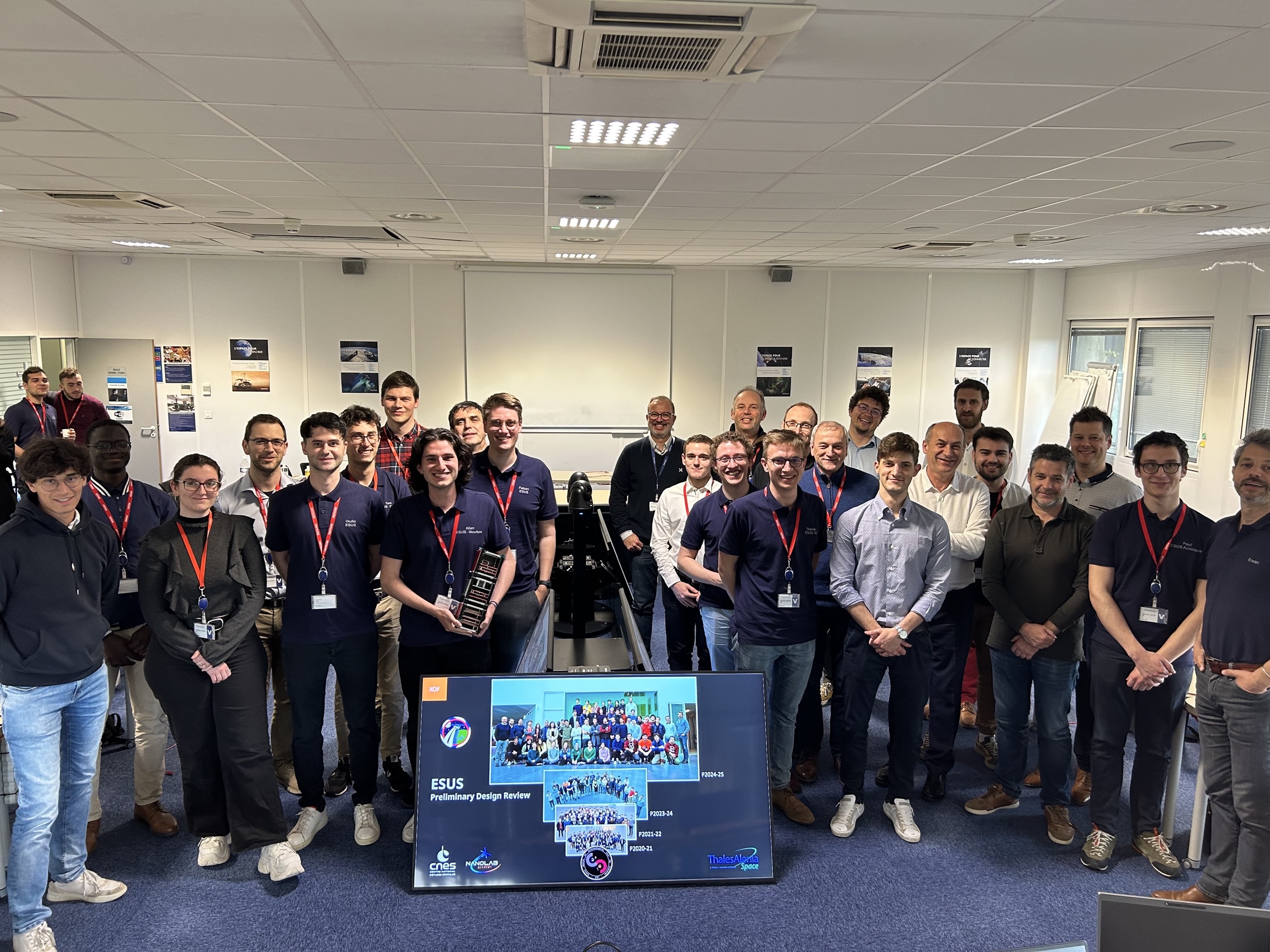
I presented these results to CNES and Thales Alenia Space, and the Phase B review was validated.
</details>